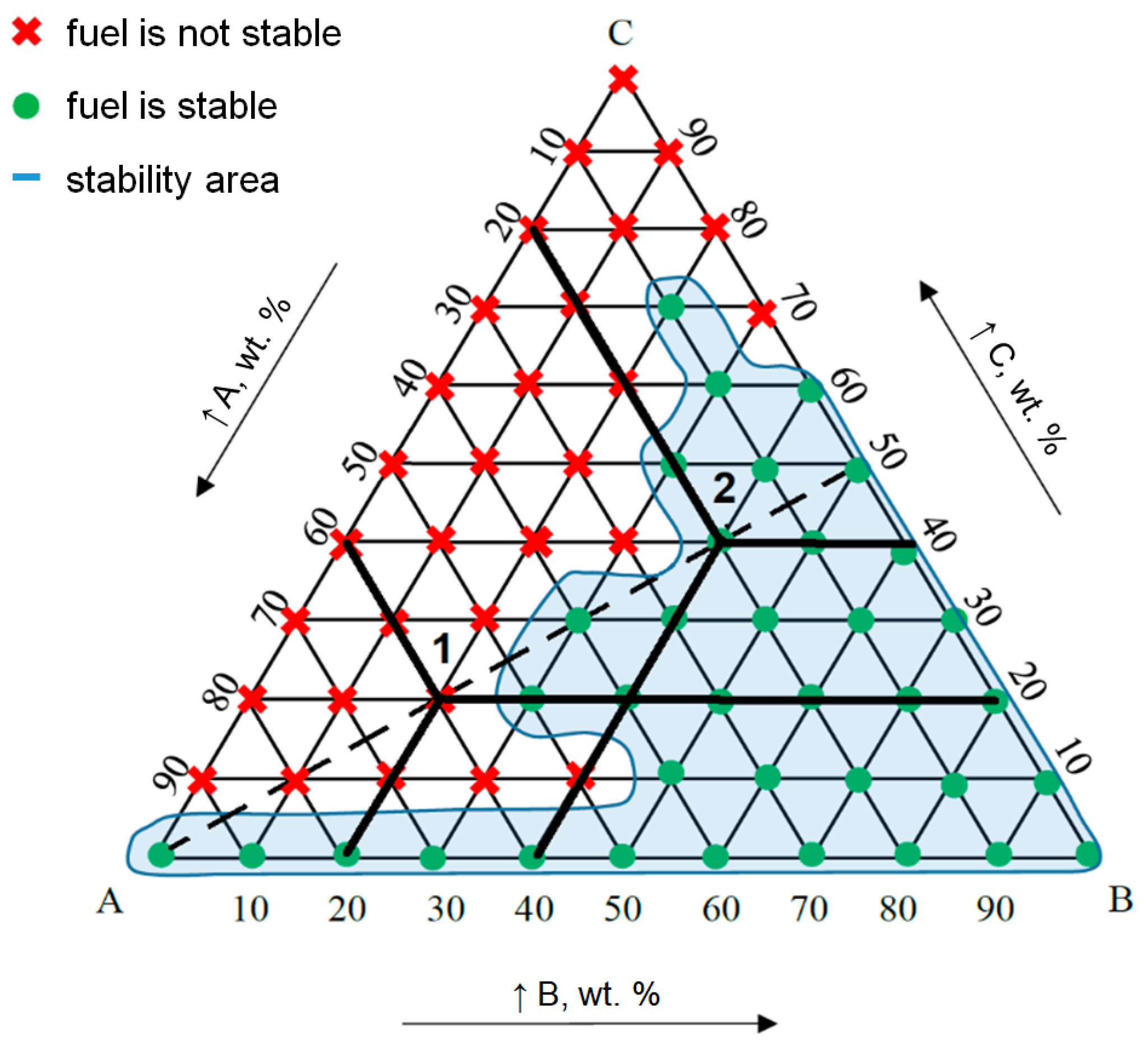

1 is a traditional pseudoternary-diagram representation of phase behavior for the pseudo-components:įig. Even so, a pseudoternary diagram is still a useful way to represent some complex phase-behavior concepts that are not so easily visualized otherwise.Ī ternary diagram represents phase behavior at a constant temperature and pressure. Pseudoternary diagrams apply rigorously only to true ternary systems, and a strictly ternary analogy may give a somewhat misleading view of the mass-transfer mechanisms that result in compositional enhancement. another, and different groupings may give somewhat different insights into phase-behavior mechanisms. Different injection processes may be better represented by one type of grouping vs. There is no particularly "right" way to divide a fluid into three pseudocomponents. The higher-molecular-weight pseudocomponent in this scheme would be the leftover C 7+ fraction. The intermediate-molecular-weight pseudocomponent might include the C 2 –C 6 hydrocarbons and perhaps CO 2 if the CO 2 is a constituent of an otherwise hydrocarbon injection solvent. A fraction of the higher-molecular-weight materialsįor example, the low-molecular-weight fraction might include methane and nitrogen and perhaps CO 2 if CO 2 is the primary injection solvent.A fraction of intermediate-molecular-weight materials.


 0 kommentar(er)
